Typical Electrical Controls:
One A/C Switch:
TYPICAL AC WIRING DIAGRAM |
||
|
|
|
Group control system:
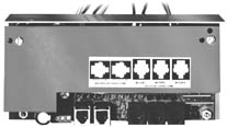
| GROUP CONTROL SYSTEM II (GCS-II) |
| DESCRIPTION | 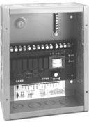 |
|
| The Group Control System-II (GCS-II) permits low voltage control of up to four
SOMFY operators with one or more switches, from one or more locations. Optional low voltage control can be
accomplished using SOMFY's Decorator Somfy-Matic™, Decorator Comfort Control or Radio Remote Control Kit. The
GCS-II offers only group control, and does not have the capability of operating each motor individually. The
Group Control System-II is UL and cUL approved. For applications requiring more than 4 motors operated by the same switch, the GCS-II can be daisy-chained by way of the low voltage switch terminals. |
| MECHANICAL SPECIFICATIONS |
| Overall Dimensions: L: 8 in. W: 10 in. D: 4 in. |
| ELECTRICAL SPECIFICATIONS | ||||||
| Voltage Ratings: | ||||||
| INPUT: | Line Voltage: | 115 VAC +/- 10% | 50/60 Hz | 20A | (6300123) | |
| 220 VAC +/- 10% | 50/60 Hz | 20A | (6300124) | |||
| Low Voltage: | 12 VDC 0.3A | |||||
| OUTPUT: | 115 VAC | 3A (Each motor) | (6300123) | |||
| 220 VAC | 3A (Each motor) | (6300124) | ||||
| Fuses (Motor) | 10A (One per two motors) | |||||
| Fuse (GCS II) | 1/2A | |||||
| Approvals: | Conforms to UL508 standard for industrial controls Complies with the National Electrical Code Standards (NEC) UL and cUL approved |
| LOW VOLTAGE CONNECTIONS |
 |
| GCS-II WIRING SCHEMATICS | ||
| Single GCS | ||
 |
|
|
| Two or more GCS's | ||
 |
||
| GCS-II WIRING DIAGRAM |
|
|
 |
|
Individual Group Control:
| INDIVIDUAL-GROUP CONTROL (IGC AND IGC/3N1) |
| DESCRIPTION | |
| The IGC provides control of one or more motors in groups and/or
individually from one or more locations. This advanced yet simple to install modular control system can be
activated manually or automatically. The heart of the system is the IGC Motor Controller used for each motor.
However, greater economy can be obtained using the IGC/3N1 version for those jobs that call for controlling
three or more motors individually or in groups. The IGC is a very flexible control system that can be configured in a variety of ways (i.e., individual window control, floor control, total building control, etc.) to meet the requirements of your customers. The Individual IGC Controller has an added feature. It is equipped with a dry contact input that can interface with a window alarm system. One typical application is for casement windows; when the window is open, the motor will not operate. This is to help prevent damage to window treatments. |
|
 |
|
| MECHANICAL SPECIFICATIONS | ||||||
| Overall Dimensions: | IGC: IGC/3N1: |
L: 3 1/2 in. L: 7 3/16 in. |
W: 3 3/8 in. W: 3 1/2 in. |
D: 2 1/4 in. D: 1 7/8 in. |
||
| IGC fits in a 2 gang masonry electrical box; | ||||||
| IGC/3N1 fits in a 4 gang masonry electrical box | ||||||
| ELECTRICAL SPECIFICATIONS | ||||||||
| Voltage Ratings: | IGC: | INPUT: | ||||||
| Line Voltage: | 115VAC +/- 10% 50/60 Hz 230VAC +/- 10% 50/60 Hz |
(6300717) (6300845) |
||||||
| Low Voltage: | 12 VDC 90mA maximum consumption | |||
| OUTPUT: | 115 VAC 5A 1/4 HP 230 VAC 5A 1/4 HP Fuse 5A |
(6300717) (6300845) |
||
| IGC/3N1: | INPUT: | ||||||||
| Line Voltage: | 115VAC +/- 10% 50/60 Hz 230VAC +/- 10% 50/60 Hz |
(6300719) (6300846) |
|||||||
| Low Voltage: | 12 VDC 185mA maximum consumption | |||
| OUTPUT: | 115 VAC 15A 1/4 HP (5A per motor) 230 VAC 15A 1/4 HP (5A per motor) Fuse 16A |
(6300719) (6300846) |
||
Approvals:
Both the IGC and IGC/3N1 conform to UL508 for industrial controls complies with the National Electrical Code Standards (NEC). UL and cUL approved. |
||||
| APPLICATION NOTES | |
| The Individual-Group Control System is compatible with other SOMFY Controls (i.e., Remote Control, Digital Timer, Decorator Somfy-Matic™, Decorator Comfort Control, etc.) and other security, computer and HVAC systems. |  |
| IGC WIRING SCHEMATIC | ||||
| M=MASTER IND=INDIVIDUAL |
||||
|
|
|||
 |
 |
 |
||
| ORDERING INFORMATION | |||
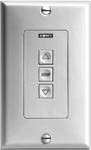 IGC Single Control Switch |
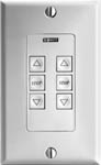 IGC Dual Control Switch |
||
IGC Modular Cable pins assigments
Remote Control Options:
Infrared:
| INFRARED SWITCH |
| DESCRIPTION | 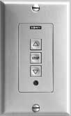 |
|
| The Infrared Switch is designed to provide remote access to many of SOMFY's standard controls. By incorporating an addressable infrared sensor into SOMFY's Decorator IGC switch, individual and master control is possible from a single infrared transmitter. The Infrared switch is compatible with the IGC, GCS-II, IGC-HB, IGC II and MCIR. Up to 15 addresses can be assigned in a variety of configurations (i.e. individual window control, room control, floor control, etc.) to meet the requirements of your customers. |
| MECHANICAL SPECIFICATIONS |
| Overall Dimensions: W: 2 3/4 in. H: 4 1/2 in. D: 1 1/4 in. |
| Typical Range in Optimal Conditions: 20ft. |
| Installs in a standard single gang electrical box. |
| OPERATING PROCEDURES |
| Connect from the modular connector on the IR Switch to the modular connector
on the IGC or GCS. On the IGC, the switch can be connected to either the Master or Individual ports. Refer
to instructions for details. Set the unit address using the rotary switch. Position 1 refers to IR address 1, and position F refers to IR address 15. Position 0 is used only for the single channel transmitter. Mount the IR Switch in a single gang box. Ensure nothing obstructs the sensor opening. Operate each motor in one direction using either the push button switch or the infrared transmitter. If the motor does not move in the correct direction, reverse the red and brown wires at the motor. Please refer to IGC or GCS instructions for further information. |
 |
| OPTIONS | ||
| SINGLE CHANNEL TRANSMITTER: A single motor (address number 0) or group can be operated by pressing either the UP or DOWN buttons on the transmitter. Pressing the center button will stop the motor at its present position. | 1 Channel IRS Transmitter Cat. No. 6300879 |
|
| EIGHT CHANNEL TRANSMITTER: This transmitter has the ability to activate up to 8 motors or groups individually. Press the address of the switch you wish to operate, then the directional command. Pressing a group command (1-4, 5-8, 1-8) and then a direction will activate all switches in the chosen group that are within transmitter range. | 8 Channel IR Transmitter Cat. No. 6300988 |
|
| 15 CHANNEL TRANSMITTER: This transmitter has the ability to control up to 15 switches (Address numbers 1-15) individually or as a group. Each individual switch is activated by first pressing the desired unit number on the transmitter and then pressing the OPEN or CLOSE buttons. Pressing the ALL button on the infrared transmitter will cause all switches within transmitter range to activate. Please refer to the transmitter instructions for further information. | 15 Channel IRC 2000 Cat. No. 6150461 15 Channel IRC 1000 Cat. No. 6150460 |
| TYPICAL APPLICATIONS |
| INDIVIDUAL CONTROL (One Channel) | |
 |
The first illustration shows a single channel transmitter controlling a single
motor. In the second illustration, an eight channel transmitter provides individual and master control. Each switch has a unique address. Any number of motors can be operated as a group using the IR Switch-GCS version. |
| INDIVIDUAL AND MASTER CONTROL |
 |
| GCS-II WIRING SCHEMATICS |
 |
Wireless radio remote control:
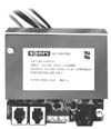
| WIRELESS REMOTE CONTROL |
| DESCRIPTION: | |
| The new SOMFY Wireless Remote Control is a single motor control designed for residential use. This unit features an integrated radio receiver and input terminals for an optional low voltage switch. For security and convenience, both transmitter and receiver are addressable, with over 1000 possible codes. The Wireless Remote Control is packaged in a weatherproof enclosure and includes watertight strain-relief fittings for wires entering the box. This single motor control is ideal for both new construction and home improvement, installing fast and easy near the motor and reducing overall wiring costs. It uses a hand-held radio transmitter that features UP, DOWN, and STOP buttons. An individual-group effect can be achieved with low voltage switches using two methods; addressing all transmitters and receivers alike and maintaining individual switches for each motor, or interconnecting the switch line and maintaining unique transmitter/receivers for each motor. | 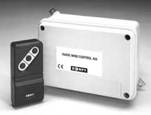 |
| MECHANICAL SPECIFICATIONS: |
| Overall Dimensions: L: 5 3/4 in. W: 4 in. D: 2 1/4 in. |
| Transmitter range in Optimal Conditions: 33ft. |
| ELECTRICAL SPECIFICATIONS: | ||
| Voltage Rating: | INPUT: | 120 VAC +/- 10% 50/60 Hz |
| OUTPUT: | 120 VAC 3.15 A 1/4 HP |
| Approvals: | The Wireless Remote Control is UL508 (pending) for industrial controls (UL, cUL) |
| CE approved | |
| Complies with the National Electrical Code (NEC) Standards |
| INSTALLATION AND OPERATING PROCEDURES | |
 |
|
| WIRING DIAGRAM | |
|
|
 |